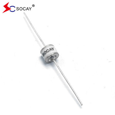
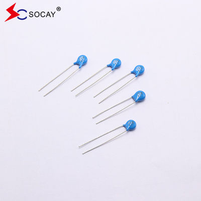
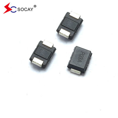
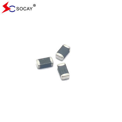
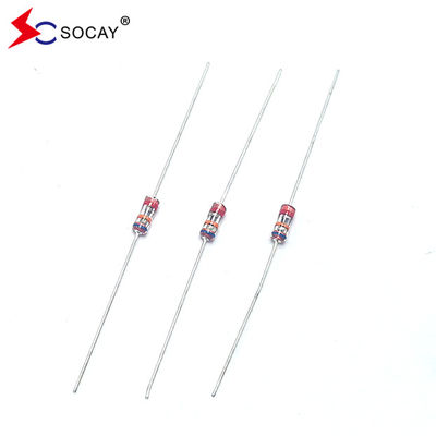
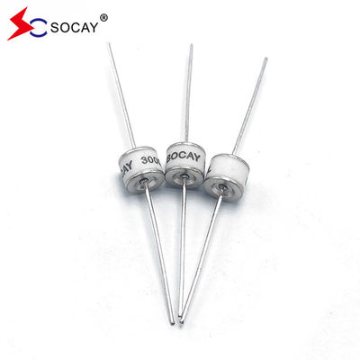
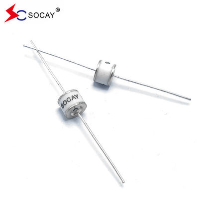
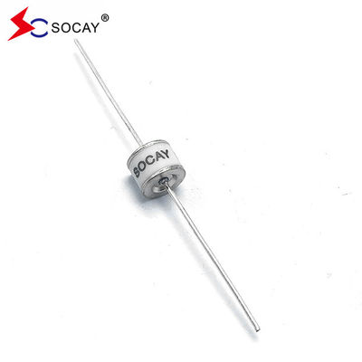
Axial Leaded Ceramic Gas Discharge Tube SC2E8-90ML RoHS Compliant

1000PCS
MOQ
Negotiable
Price
Axial Leaded Ceramic Gas Discharge Tube SC2E8-90ML RoHS Compliant
Features Gallery Product Description Request A Quote
Features
Specifications
Key Words: Lightning Arrester
Footprint: φ8*6mm
DC Spark-over Voltage @100V/μs: 90V±20%
Max. Spark-over Impulse Voltage @100V/μs: 500V
Max. Spark-over Impulse Voltage @1KV/μs: 600V
Min. Insulation Resistance: 1GΩ (@50V)
Nom. Impulse Discharge Current: 10KA
Max. Impulse Discharge Current: 20KA
Usage: Lightning Protection
Highlight:

RoHS Gas Discharge Tube

,

Gas Discharge Tube SC2E8-90ML

,

Axial Leaded Ceramic Discharge Tube

Basic Infomation
Place of Origin: Shenzhen, Guangdong, China
Brand Name: SOCAY
Certification: UL,REACH,RoHS,ISO
Model Number: SC2E8-90ML
Payment & Shipping Terms
Delivery Time: 7-12 work days
Product Description

90V±20% Axial Leaded Ceramic Gas Discharge Tube SC2E8-90ML, RoHS Compliant


DATASHEET:   SC2E8_v91.1.pdf


Selection principles for ceramic gas discharge tubes


1. The prerequisite for the addition of ceramic gas discharge tubes is that the lower limit of the DC breakdown voltage of the ceramic gas discharge tube must be higher than the maximum normal operating voltage in the circuit, so that it cannot affect the normal operation of the circuit.
2. The overholding voltage of the ceramic gas discharge tube should be as high as possible to ensure that the working voltage in the circuit will not cause continuous conduction. When the overvoltage in the circuit disappears, ensure that the ceramic gas discharge tube is extinguished in time, otherwise it will affect the normal operation of the circuit.
3. Ensure that the impact breakdown voltage of the ceramic gas discharge tube must be lower than the highest instantaneous voltage that the circuit can withstand.
4. According to the intensity of the impulse current that may enter the line, determine the impulse current resistance capability that the selected discharge tube must achieve.
5. When necessary, the ceramic gas discharge tube should be equipped with an appropriate short-circuit device, FS device, also called a failure protection device.


Axial Leaded Ceramic Gas Discharge Tube SC2E8-90ML RoHS Compliant 0

Part Number Marking

DC Spark-

over Voltage

Maximum Impulse Spark-over Voltage Minimum Insulation Resistance Maximum Capacitance Arc Voltage Service Life
             

Nominal

Impulse Discharge Current

Max Impulse Discharge Current

Nominal

Impulse Discharge Current

Impulse Life
    @100V/S @100V/μs @1KV/μs   @1MHz @1A

@8/20μs

±5 times

@8/20μs

1 time

@50Hz

1 Sec

10 times

@10/1000μs

300 times

SC2E8-75M

SC2E8-75ML

SC2E8-75MSMD

SOCAY

75M

75V±20% <500V <600V 1 GΩ (at 25V) <1.5pF ~15V 10KA 20KA 10A 100A

SC2E8-90M

SC2E8-90ML

SC2E8-90MSMD

SOCAY

90M

90V±20% <500V <600V 1 GΩ (at 50V) <1.5pF ~15V 10KA 20KA 10A 100A

SC2E8-150M

SC2E8-150ML

SC2E8-150MSMD

SOCAY

150M

150V±20% <500V <600V 1 GΩ (at 50V) <1.5pF ~20V 10KA 20KA 10A 100A

SC2E8-230M

SC2E8-230ML

SC2E8-230MSMD

SOCAY

230M

230V±20% <600V <700V 1 GΩ (at 100V) <1.5pF ~20V 10KA 20KA 10A 100A

SC2E8-250M

SC2E8-250ML

SC2E8-250MSMD

SOCAY

250M

250V±20% <700V <800V 1 GΩ (at 100V) <1.5pF ~20V 10KA 20KA 10A 100A

SC2E8-300M

SC2E8-300ML

SC2E8-300MSMD

SOCAY

300M

300V±20% <800V <900V 1 GΩ (at 100V) <1.5pF ~20V 10KA 20KA 10A 100A

SC2E8-350M

SC2E8-350ML

SC2E8-350MSMD

SOCAY

350M

350V±20% <800V <900V 1 GΩ (at 100V) <1.5pF ~20V 10KA 20KA 10A 100A


Axial Leaded Ceramic Gas Discharge Tube SC2E8-90ML RoHS Compliant 1


Axial Leaded Ceramic Gas Discharge Tube SC2E8-90ML RoHS Compliant 2


About GDT
Gas discharge tubes work according to the gas physics principle of high-efficiency arc discharge. From an electrical perspective, a gas discharge tube is equivalent to a pressure-sensitive switch. Once the voltage applied to the discharge tube exceeds the breakdown voltage, an arc will form in the sealed discharge area within nanoseconds. High surge current handling capabilities and an arc voltage that is almost independent of current short circuit overvoltages. When the discharge ends and the discharge tube goes out, the internal resistance immediately returns to several 100 MΩ. Therefore, gas discharge tubes meet almost all the requirements of the protected components. It can reliably limit overvoltage within the allowable value range, and under normal operating conditions, due to its high insulation resistance and low capacitance characteristics, the discharge tube will essentially have no impact on the protected system.


Classification of ceramic gas discharge tubes
1. According to the number of electrodes, commonly used gas discharge tubes are divided into diode discharge tubes and triode discharge tubes. Most of their packaging materials are ceramics, so they are called ceramic discharge tubes.
2. According to the appearance size, commonly used gas discharge tubes are divided into chip discharge tubes and plug-in discharge tubes.
3. According to the product pulse voltage, commonly used gas discharge tubes are divided into conventional pulse discharge tubes and low pulse discharge tubes.


Recommended Products
Get in touch with us
Contact Person : Sun
Tel : +8618126201429
Fax : 86-755-88362681
Characters Remaining(20/3000)